 Noah Spiegelman
Project
RASTICrane
ME416, Boston University · Fall 2026
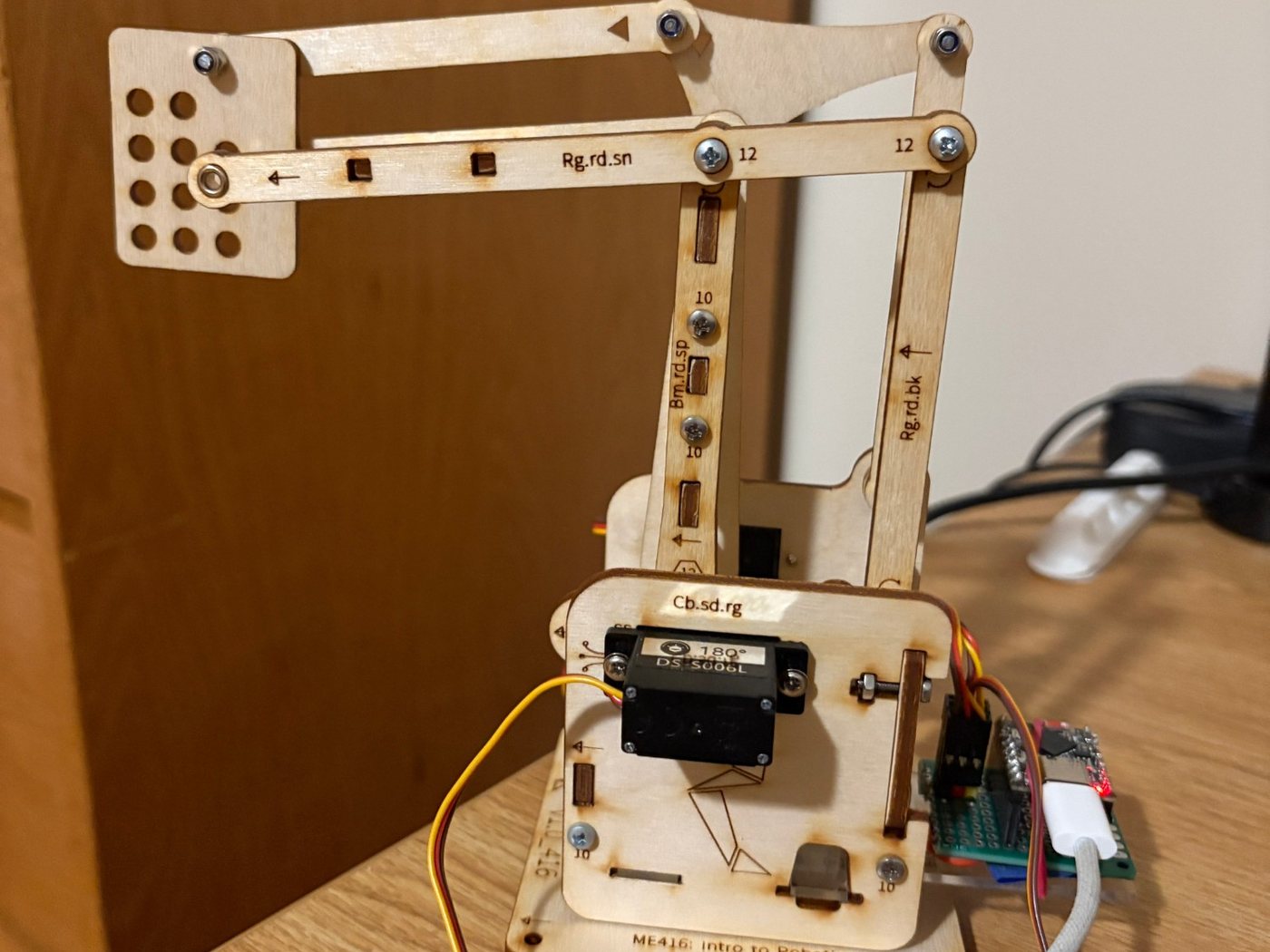
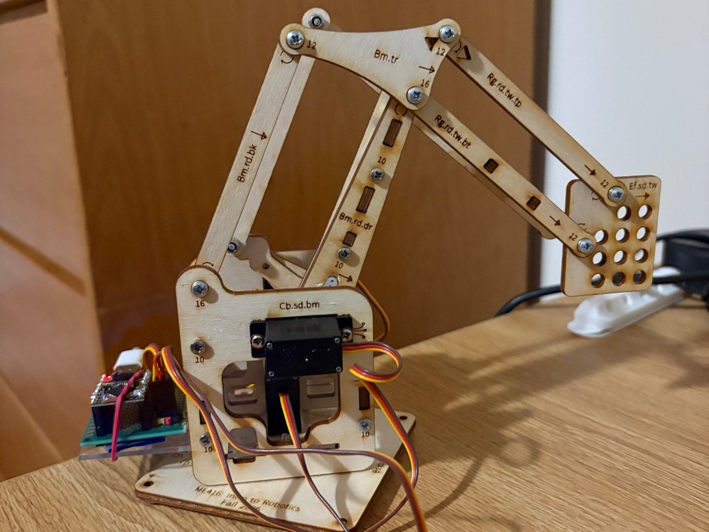
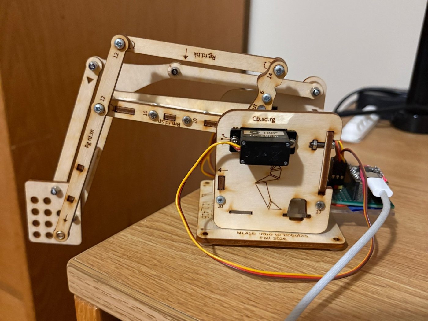
A wooden robotic arm built for ME416: Intro to Robotics, with three servos driven by an ESP32. The instructions and laser-cut files were provided, so the challenge wasn't designing an arm. It was getting the hardware and software to work together in about a week. Still in progress: next, it will pick up rubber stamps and stamp names onto paper.
- Role
- Assembly, soldering and servo control
- Tools
- ESP32, Arduino (C++), Servo motors, Soldering, MQTT
- Mechanical
- Embedded

Problem
The arm's design, instructions and laser-cut files were all provided to us, so the challenge of this project wasn't designing a robotic arm. It was to struggle through and persevere, working with hardware and software to make this work in a short amount of time, about a week.
Robotics is difficult because if one part of the robot doesn't work, none of it does. This project took a lot of effort and made me adapt over and over.
Approach
The laser-cut file was designed for a thinner piece of wood than the one I used, so I had to sand down a lot of the connections and jam some of the others together. I also had to sand the tight servo horn pockets that were cut out of the wood.
The joints took tuning too. They had to be loose enough to rotate freely, but not so loose that they came undone.
The ESP32 sits on a PCB that I soldered by hand. The pin headers had to be perfectly vertical for the ESP32 to fit onto the board, and the connections were so close together that too much solder would spill over while too little would give a poor electrical joint. We ran continuity tests and resoldered whenever one failed.
Getting the ESP32 to communicate over MQTT took the longest. A good chunk of the class, along with the professor, worked together in the robotics maker space from noon until 11:30 at night trying to figure it out. The cause turned out to be that some of the wood was blocking the ESP32's Wi-Fi chip, and that requirement was removed.
We were instructed to write all the code with AI, for two reasons: AI is going to be part of our work anyway, so we might as well use it to our advantage, and there wasn't nearly enough time to write it all by hand.
We had discretion over how to move and control the arm, so I chose to select a servo and an angle and send the arm there. The sketch runs on the ESP32 and drives three servos, one 300° and two 180°. The snippets below show how it works.
The full range of a servo isn't necessarily the full range of the robot. If I sent an angle too far one way or the other, the arm crashed into itself or the surface it sat on and the servo stalled, so I had to be careful about which angles I commanded.
Results
The arm is assembled and moving under servo control (video above), and the project is still in progress. The biggest lesson was persistence: a tight fit, a bad solder joint or a blocked antenna can stop the whole robot, and each one had to be found and fixed.
Next, the arm becomes a stamp machine for the course's second lab. A magnet on the end effector lifts rubber stamps by their steel discs, inks each one on an ink pad, presses it onto a sheet of paper and returns it to the rack, one letter at a time, until our names are on the page. Nothing is measured by hand while it runs, so it all has to come through the camera.
That means calibrating the camera and finding AprilTags on the base plate, the stamps, the ink pad and the paper. A homography from the base tag turns pixels into positions on the table, and inverse kinematics turns those positions into servo commands sent to the arm over MQTT. We will run the same code on both of our arms and compare how far each letter lands from where it was commanded.
Code
void stepToUs(ServoUnit &s, float targetUs) {
  while (abs(targetUs - s.currentUs) > STEP_US) {
    s.currentUs += (targetUs > s.currentUs) ? STEP_US : -STEP_US;
    writePulseUs(s.pin, s.currentUs);
    delay(STEP_DELAY_MS);
  }
  s.currentUs = targetUs;
  writePulseUs(s.pin, s.currentUs);
}
Each servo remembers where it currently is. To move, it steps toward the target pulse width 7 microseconds at a time with an 8 millisecond pause between steps, so the arm glides instead of snapping to position. Those two constants set the speed.
void moveServo(int index, float angle) {
  ServoUnit &s = servos[index];

  if (angle < 0 || angle > s.maxAngle) {
    // print an error and ignore the command
    return;
  }

  float targetUs = mapFloat(angle, 0, s.maxAngle, MIN_US, MAX_US);
  stepToUs(s, targetUs);
}
A command names a servo and an angle. The angle is checked against that servo's limit (300° for the first servo, 180° for the other two), converted to a pulse width between 500 and 2500 microseconds, and then eased there with the function above.
if (line.equalsIgnoreCase("reset")) {
  // Retract distal joints first so the arm is folded
  // before the shoulder swings
  const int resetOrder[3] = {2, 1, 0};
  for (int k = 0; k < 3; k++) {
    stepToUs(servos[resetOrder[k]], 1500);
  }
  return;
}

int servoNum;
float angle;
int parsed = sscanf(line.c_str(), "%d %f", &servoNum, &angle);
// ...checks that both values were read and servoNum is 1-3...
moveServo(servoNum - 1, angle);
The sketch reads a line over serial, such as "2 90" to send the second servo to 90°. Typing "reset" returns every servo to its center position, moving the outer joints first so the arm folds up before the shoulder swings and doesn't crash into anything.
Gallery