Project
Ambient Temperature Sensor
Boston University · Jan 2025 – May 2025
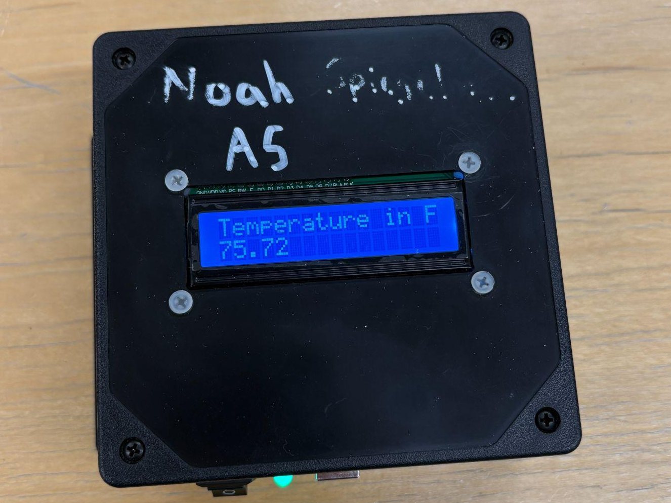
A battery-powered room temperature monitor that I took from a CAD model to a finished, enclosed device. A TMP36 sensor and an Arduino Uno show the temperature in °F on an LCD, with a red LED and buzzer that alert when the reading drops below 70 °F or rises above 75 °F.
- Role
- CAD, fabrication and Arduino programming
- Tools
- Arduino Uno, TMP36 sensor, CAD, Tinkercad Circuits, 3D printing, Soldering
- Embedded
- Mechanical
Problem
The goal was a device that shows the current room temperature in real time and alerts the user when it moves outside a comfortable range, while building hands-on practice in circuit design, microcontroller programming, CAD and system integration.
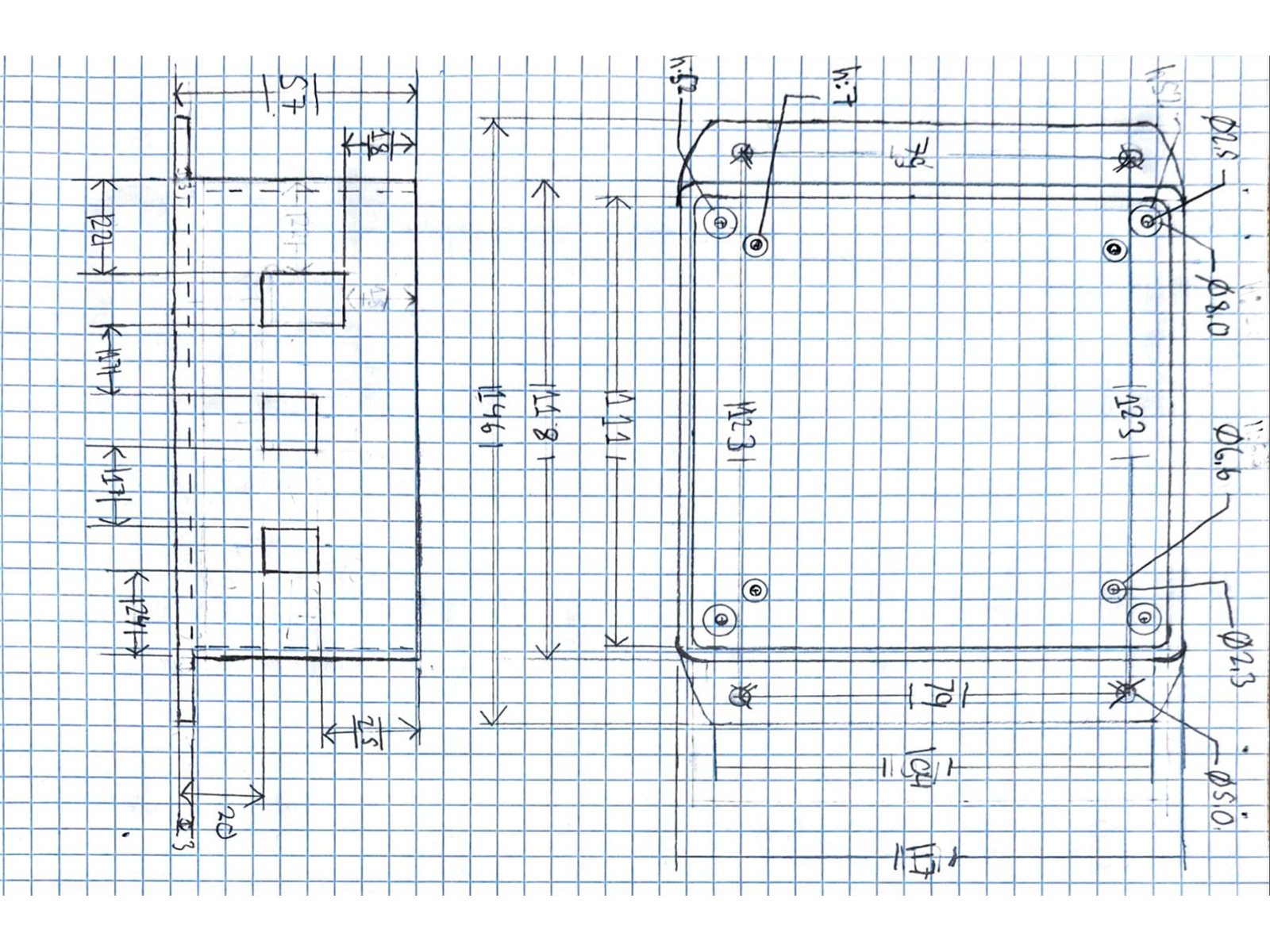
Everything had to fit inside a supplied ABS enclosure (117 × 146 × 57 mm), on a fixed schedule.
Approach
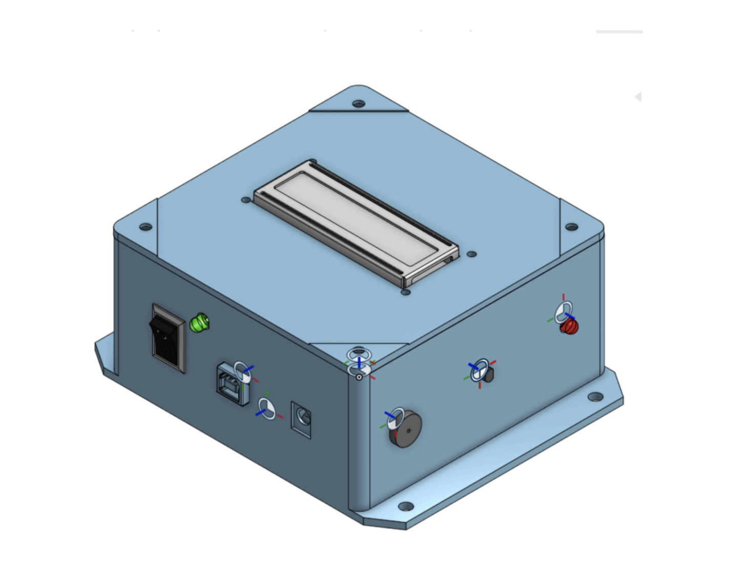
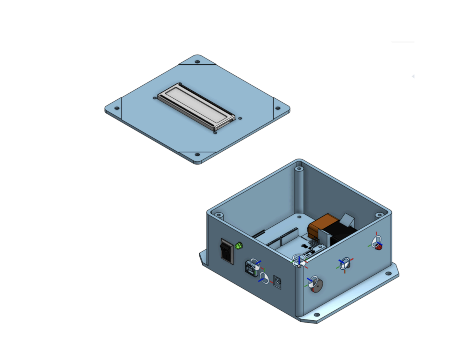
I measured every component and drew dimensioned sketches, then modelled the whole device in CAD, with every part of the final design, before starting fabrication.
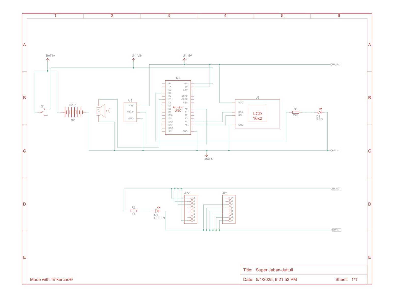
A TMP36 sensor feeds an Arduino Uno, which converts the voltage to a temperature in °F, shows it on a 16×2 I2C LCD, lights a green status LED, and flashes a red LED and sounds a piezo buzzer whenever the reading is below 70 °F or above 75 °F.
I sized the LED resistors with KVL and Ohm's law (220 Ω for the red LED at about 14.6 mA, 1 kΩ for the green at about 2.8 mA), and chose a 9 V battery because the Arduino needs a 7 to 20 V supply.
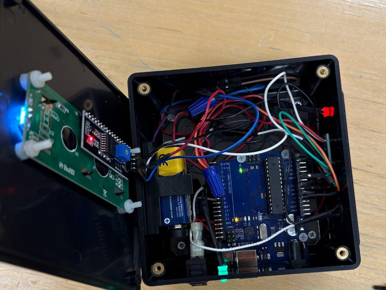
For fabrication I laid the parts out in the box first, then soldered the circuit with 22 AWG wire instead of jumper wires. Twist-nut caps share the power and ground connections, spade connectors attach the switch, and 3D-printed holders secure the batteries. Screws, solder and hot glue hold everything in the enclosure.
Results
A finished, fully enclosed monitor that reads and displays the room temperature and the red LED and buzzer alert outside a 70 to 75 °F comfort range.
The circuit draws about 86.5 mA, which gives roughly 6 hours on a 500 mAh 9 V battery.
The main limitations were battery life, the size of the supplied materials and the schedule. For a wall-mounted unit I would use a permanent power supply, smaller components (a bare microcontroller chip instead of the Arduino, in a smaller housing) and wireless software updates, so the device doesn't have to be taken down to fix bugs.
Gallery