Project
Four-Bar Axe Linkage
ME357, Boston University · Fall 2025
A CAD and motion-study project for ME357: a four-bar linkage in which a turning crank swings an axe-shaped rocker down onto a stump. The whole motion stays inside a standard 8.5 × 11 in sheet of paper.
- Role
- Design, CAD and motion study
- Tools
- SolidWorks, SolidWorks motion study, Engineering drawings
- Mechanical
- Simulation
Problem
The assignment was to design a uniquely shaped four-bar linkage in CAD and run a motion study on it. The entire range of motion had to stay within a standard 8.5 × 11 in sheet of paper.
Approach
I gave the linkage a theme. The rocker is an axe, the base carries a stump and my name, and a crank drives a coupler that swings the axe down onto the stump.
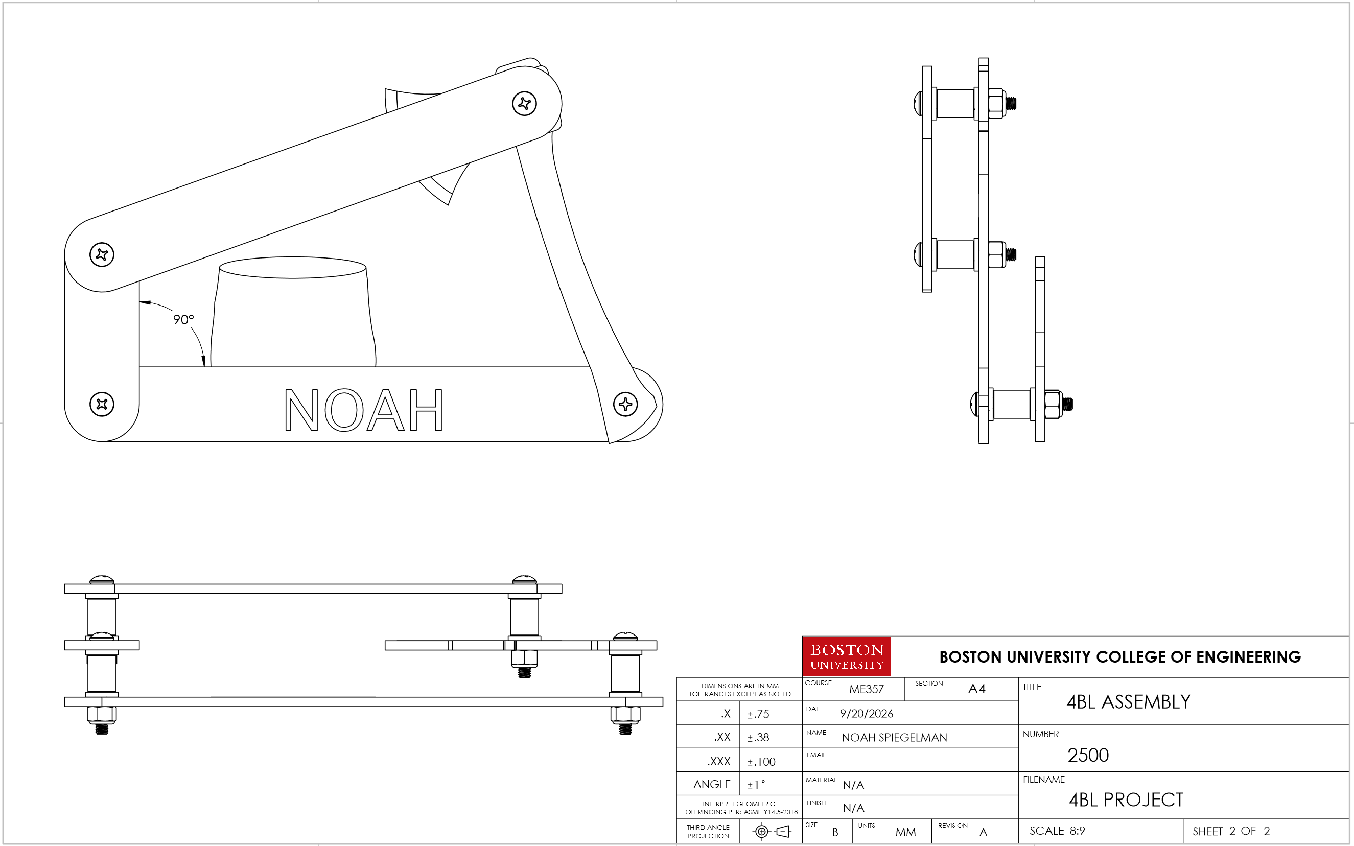
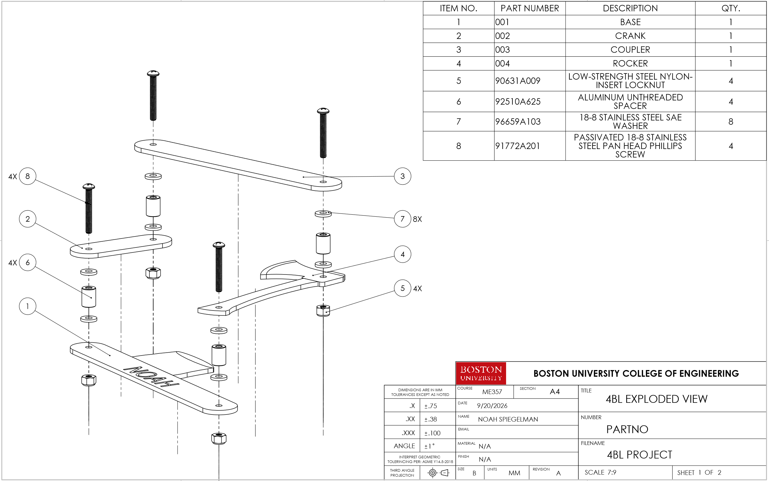
The mechanism has four custom parts (base, crank, coupler and rocker) joined at four pivots. Each pivot is a pan-head screw through a stack of washers and an aluminum spacer, secured with a nylon-insert locknut. The links sit in stepped layers so they can move past each other.
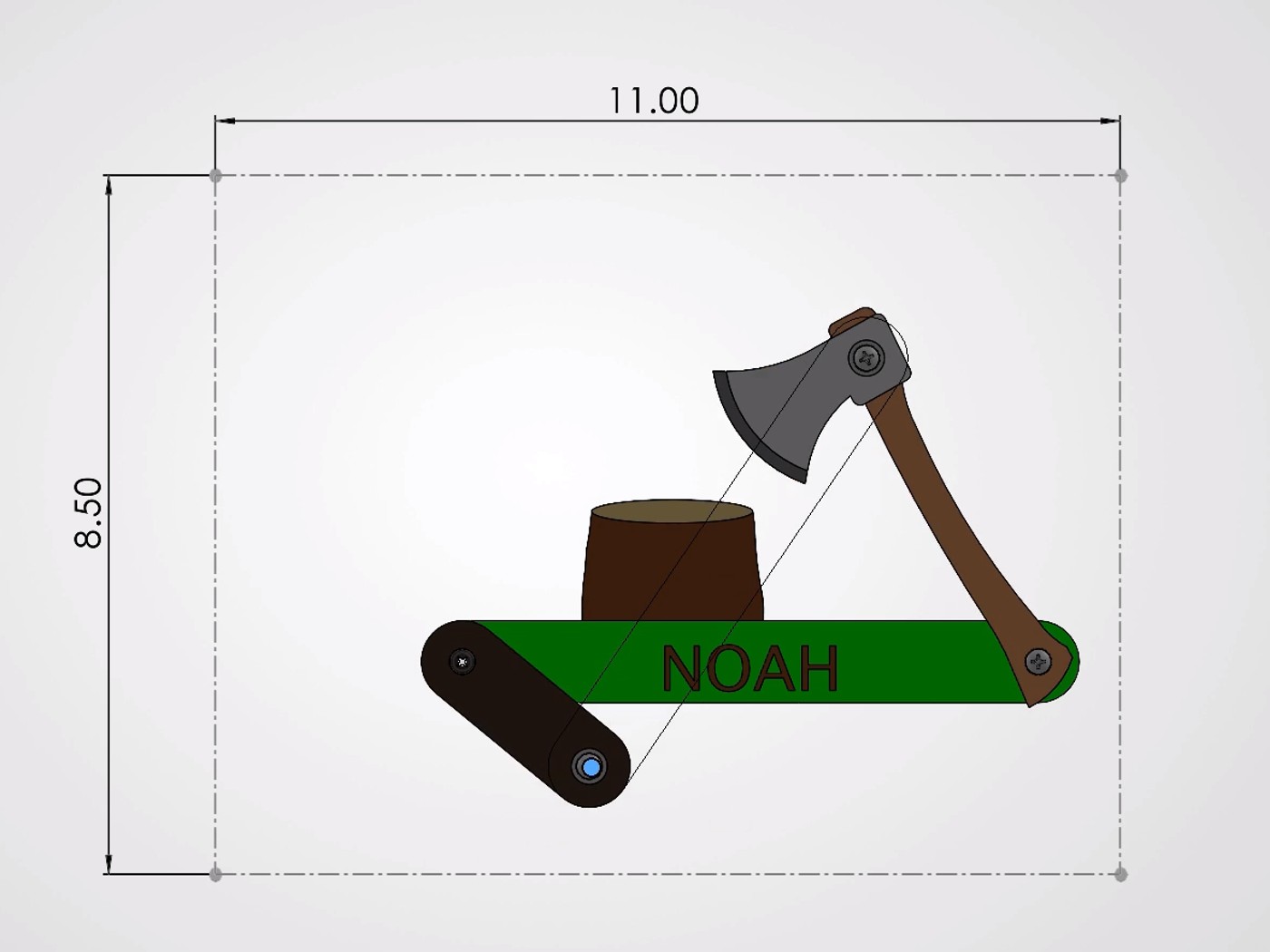
In the SolidWorks motion study I drove the crank around and watched the axe swing. An 11 × 8.5 in boundary is drawn on the view, so I could check that no part leaves the page at any point in the cycle.
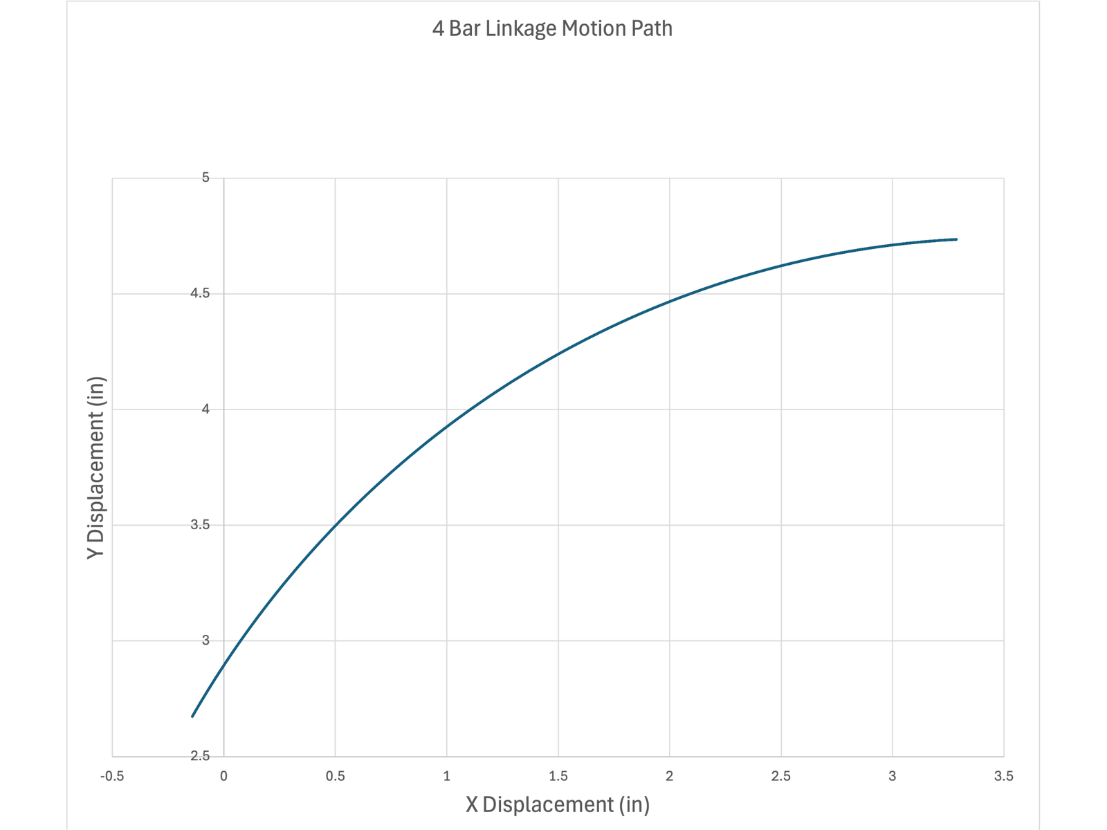
I traced the pin where the coupler meets the rocker, exported its X and Y position (126 points over one cycle) and plotted it. The points fall on a circular arc of radius 4.24 in, centered on the rocker's ground pivot, which is the path a point on the rocker must follow. The pin swings about 56° between X = -0.14 in, Y = 2.67 in and X = 3.29 in, Y = 4.74 in, and the path closes back on its starting point after each cycle.
I documented the design with an exploded view and bill of materials, and an assembly drawing with front, side and bottom views.
Results
The motion study shows the whole linkage staying inside the 8.5 × 11 in boundary through its full cycle, with the axe head landing on the stump each time around.
Gallery