Project
Point-to-Point Communication System
EK 210, Boston University · Sep 2025 – Dec 2025
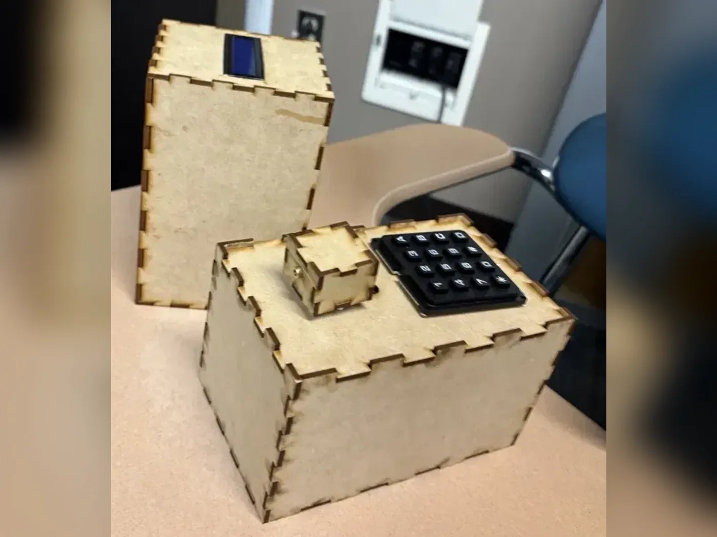
A four-person team project that sends typed messages across a room as laser-pulsed Morse code. A keypad and Arduino encode the message, a servo aims the laser, and a photoresistor receiver decodes it onto an LCD, with no computer involved.
- Role
- Receiver modelling, housing CAD and testing (team of 4)
- Tools
- Arduino Uno, Photoresistor, Servo motor, Tinkercad Circuits, Laser cutting, 3D printing
- Embedded
- Mechanical
Problem
The client brief called for two units that communicate by light with no laptop involved: a steerable transmitter that sends any of 10 characters or codewords, and a receiver that decodes and displays them. It had to work at 5 ft or more, keep each unit smaller than a shoe box, and run without a reset between messages. We framed the users as responders in remote or network-limited places where Wi-Fi is unavailable.
A pairwise comparison chart ranked reliability and durability first, then ease of use, then cost and size, with a cost target of $200 or less.
Approach
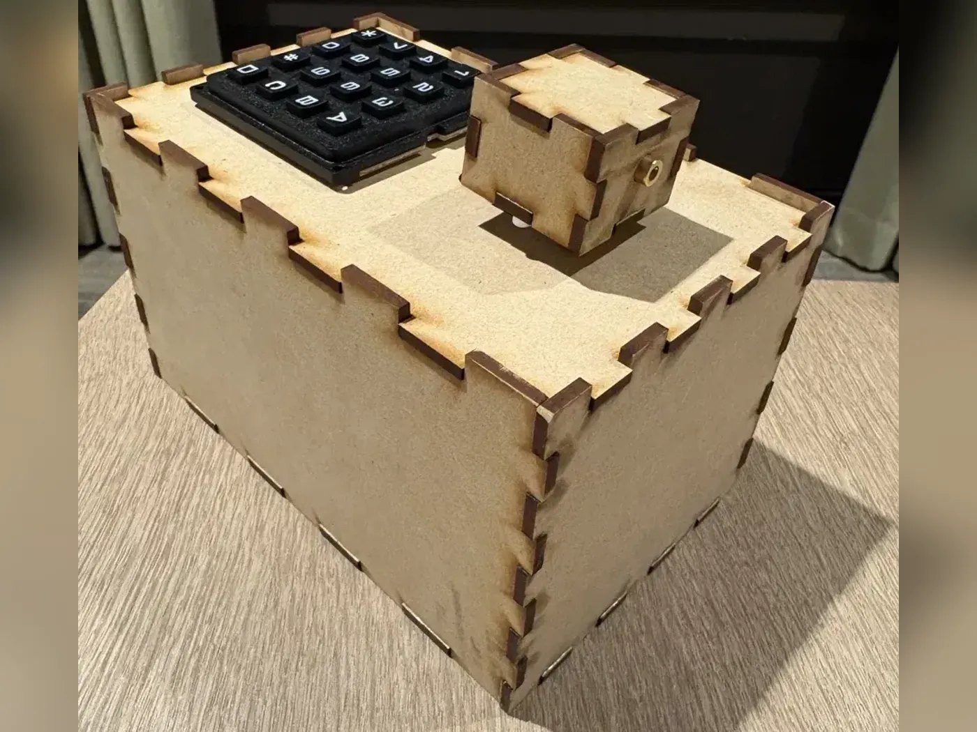
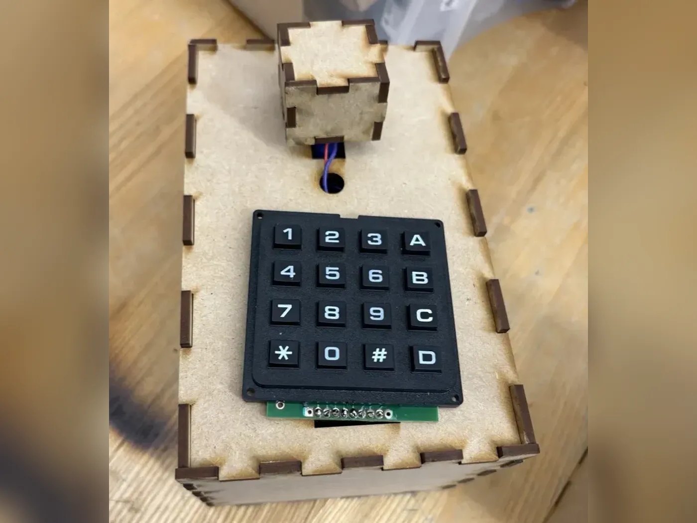
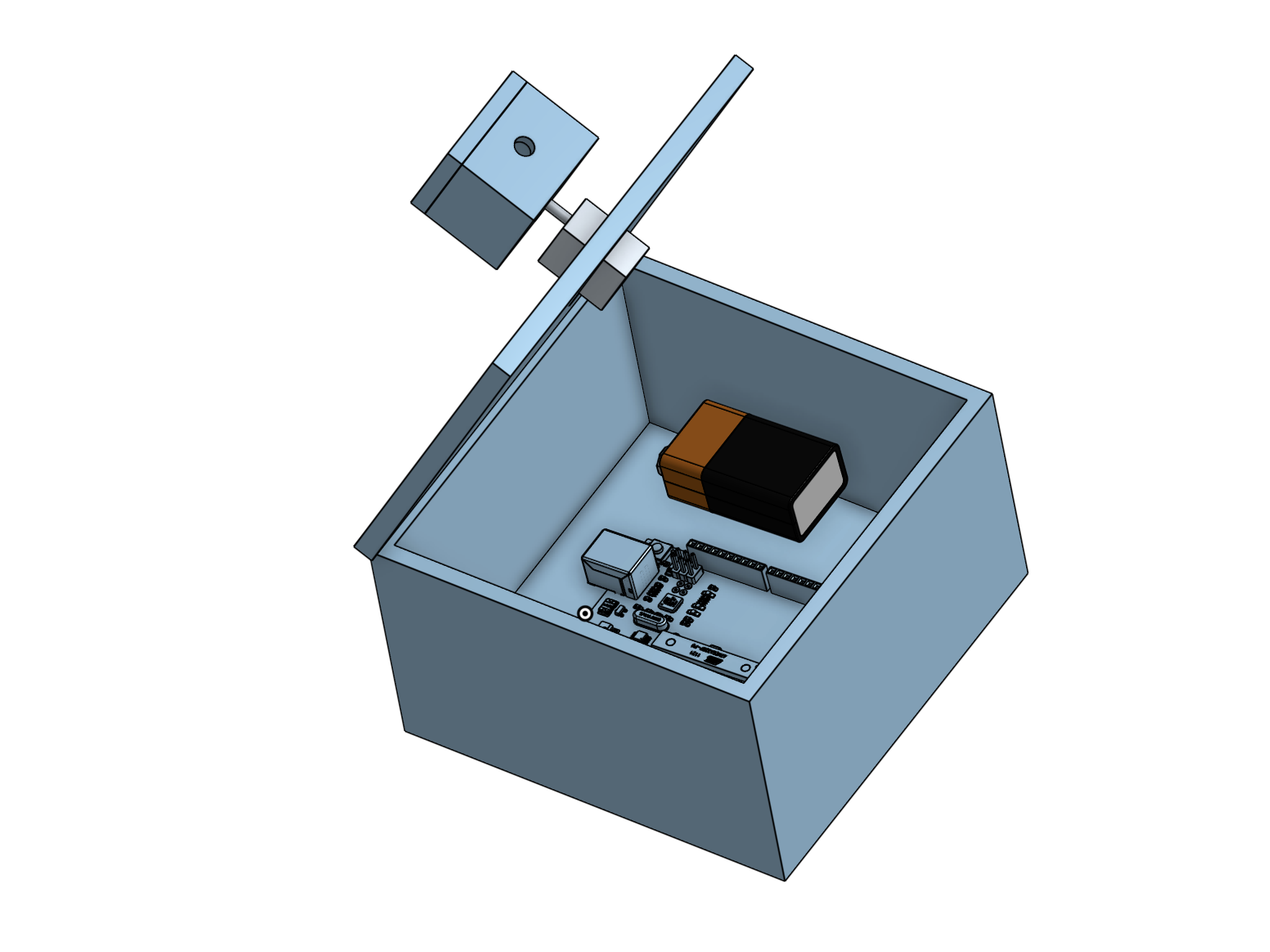
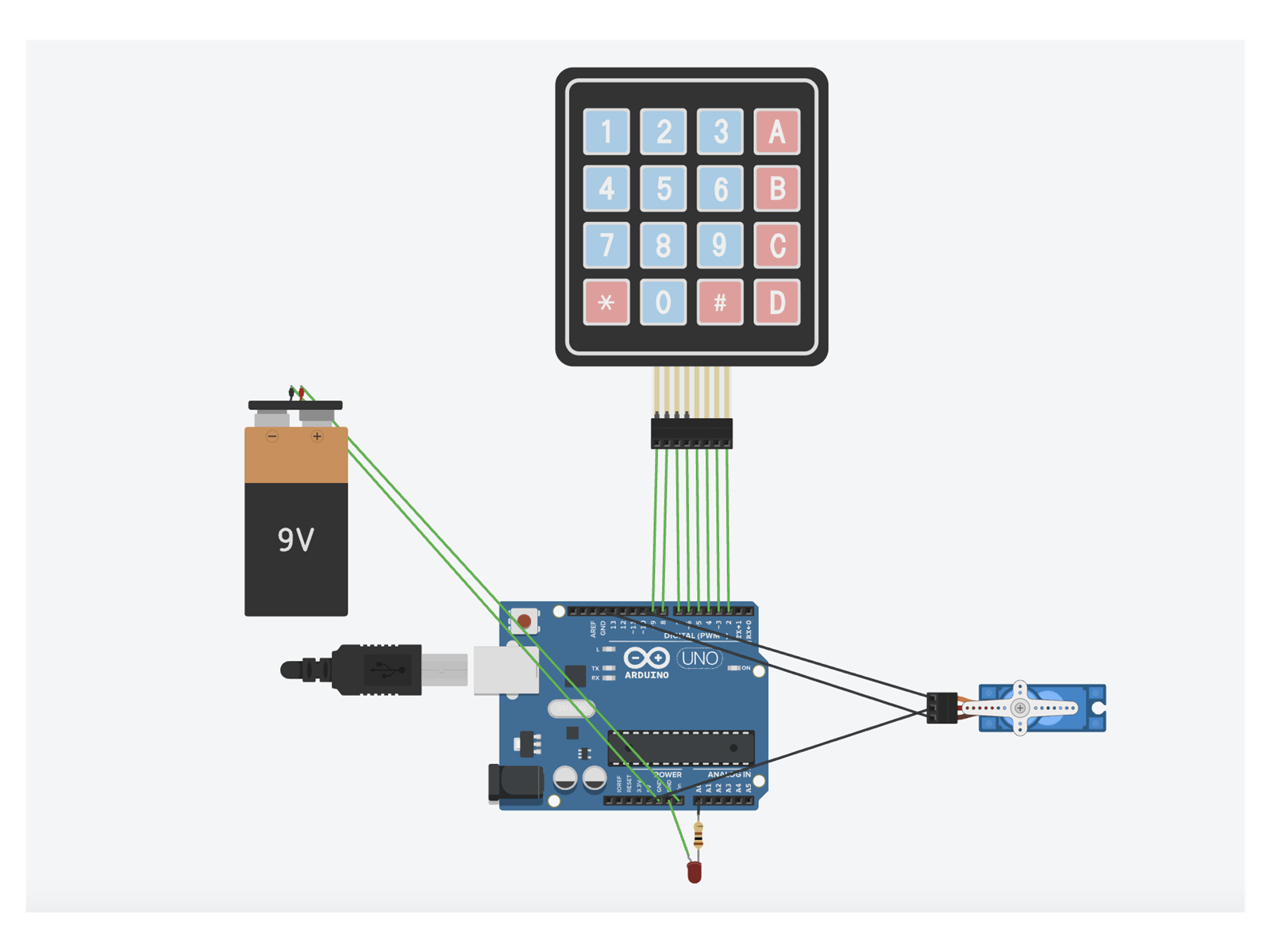
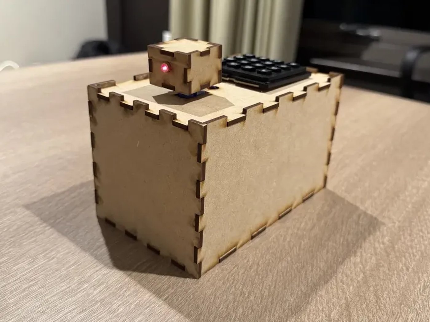
The transmitter takes input from a 16-key keypad. An Arduino Uno turns each character into timed Morse pulses and drives a 650 nm, 5 mW laser in a small housing mounted on an S51 micro servo, which steers the beam.
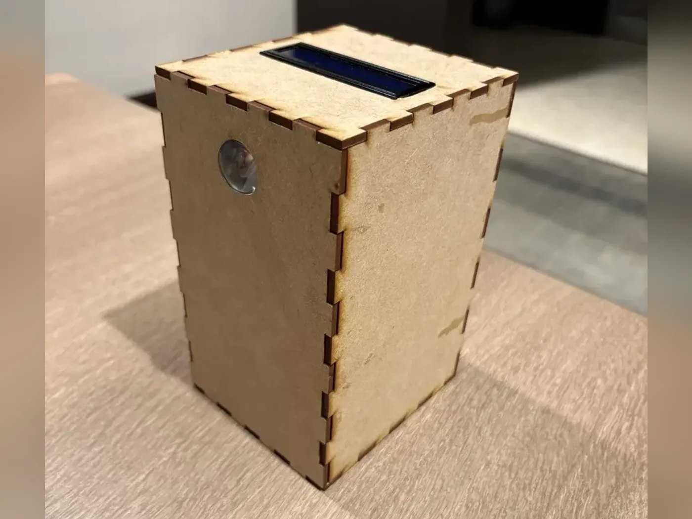
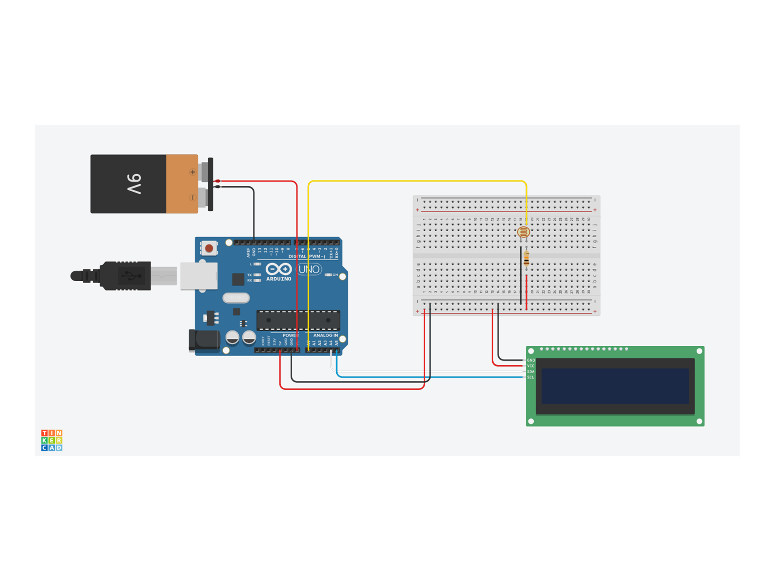
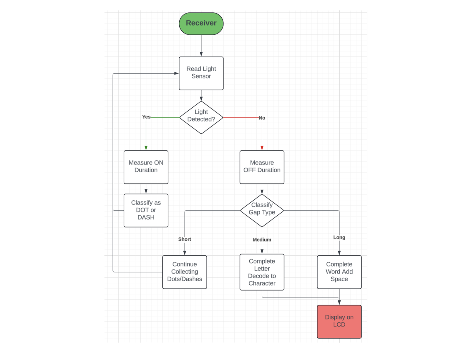
The receiver has a 20 mm plano-convex lens window on its front, and its photoresistor, in a 10 kΩ voltage divider, sits inside a light-isolating enclosure. A second Arduino times each pulse, separates dots, dashes and gaps, decodes them into characters and shows the message on a 16×2 LCD.
Before building, I worked with a teammate to model the receiver from the photoresistor's datasheet. We calculated the divider output across light levels, then bench-tested it by flashing Morse code with a phone flashlight and reading the decoded output over serial. We also compared a photoresistor with a photodiode and chose the photoresistor for more reliable signal changes, and compared a servo with a stepper and chose the servo for smoother, lower-power aiming.
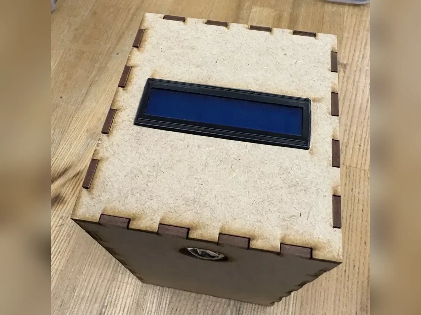
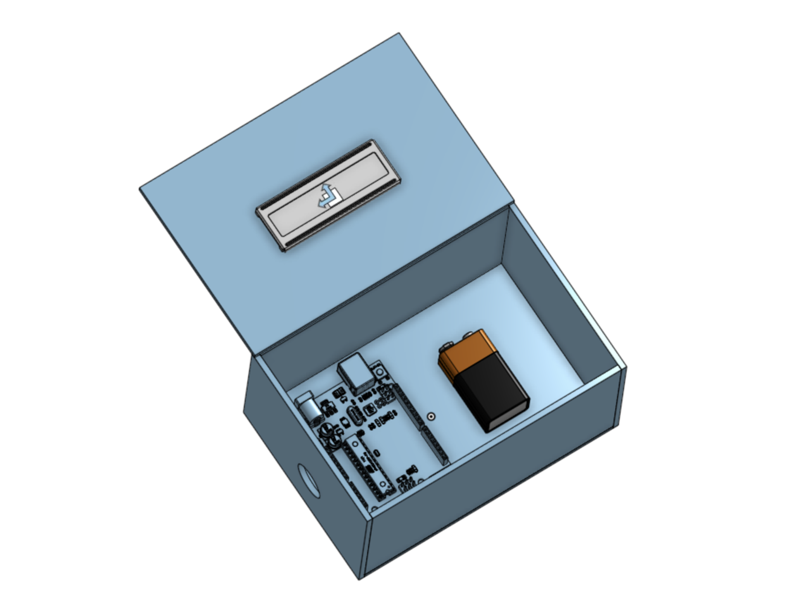
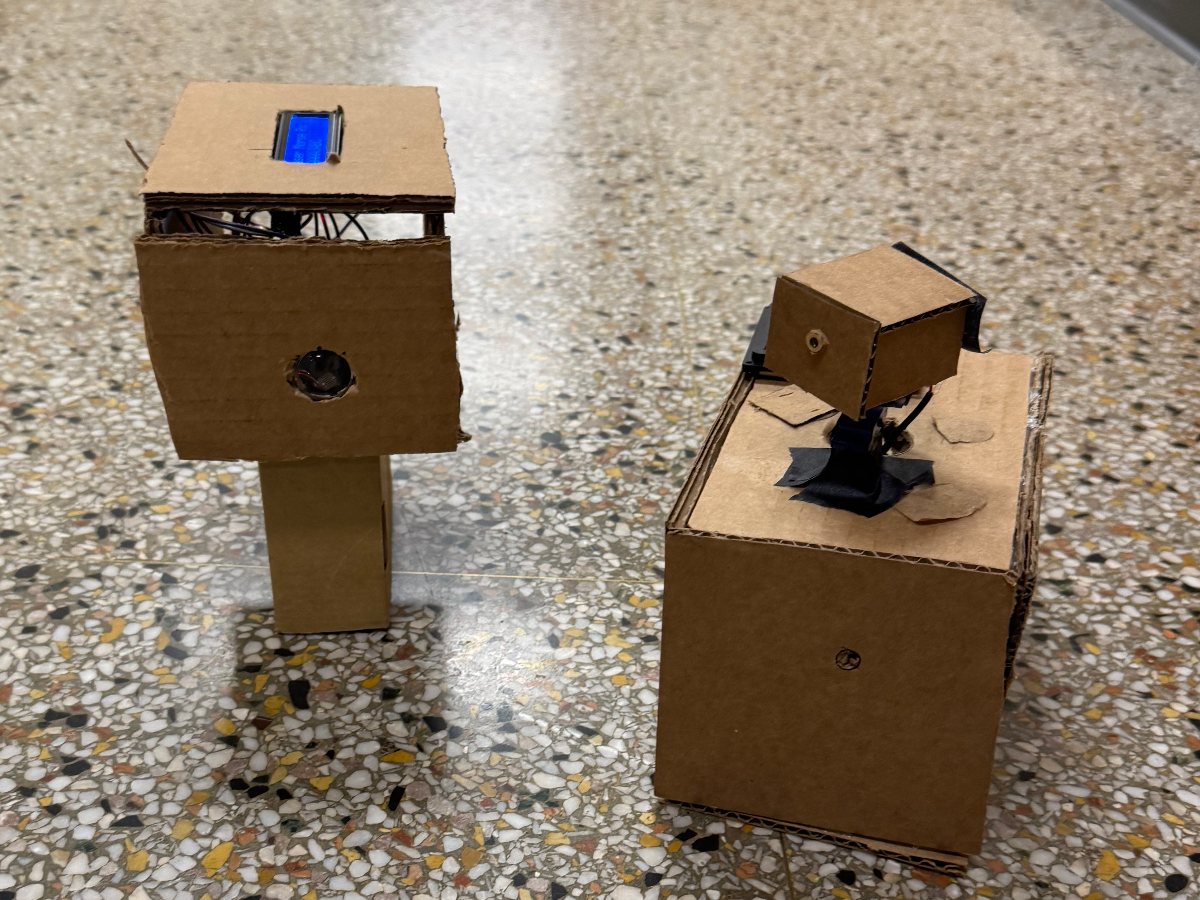
We designed the housings in CAD and laser-cut the panels, which join with interlocking finger joints. We tested each subsystem on its own before integrating, and checked the power budget for a 9 V battery.
Results
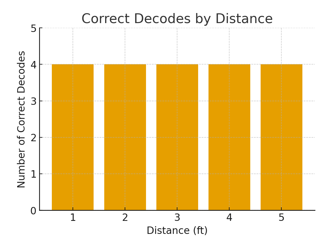
The system decoded all 10 required commands with 100% accuracy at distances of 5+ ft, with under 1.5 seconds of latency. In a distance test, 20 of 20 messages (cat, abc, dog and hello, at 1 to 5 ft) decoded correctly. The transmitter steers through 90° under motor control, and both units are fully enclosed.
The parts cost $103.76 against the $200 target. Estimated battery life on a 9 V battery is about 5 hours for the receiver and about 2 hours for the transmitter.
Lessons learned: Morse timing has to be tuned to the sensor's response time, and a few degrees of misalignment dropped the signal completely. Servo current spikes occasionally reset the Arduino in early tests, which taught us to budget power and consider capacitors or separate rails. Testing subsystems separately made debugging much faster.
Next steps we identified: a QWERTY keyboard for faster typing, a weatherproof housing, and a lens setup that gives the receiver a wider target.
Gallery