Project
Rocket Nozzle
BURPG · Boston University · Fall 2024
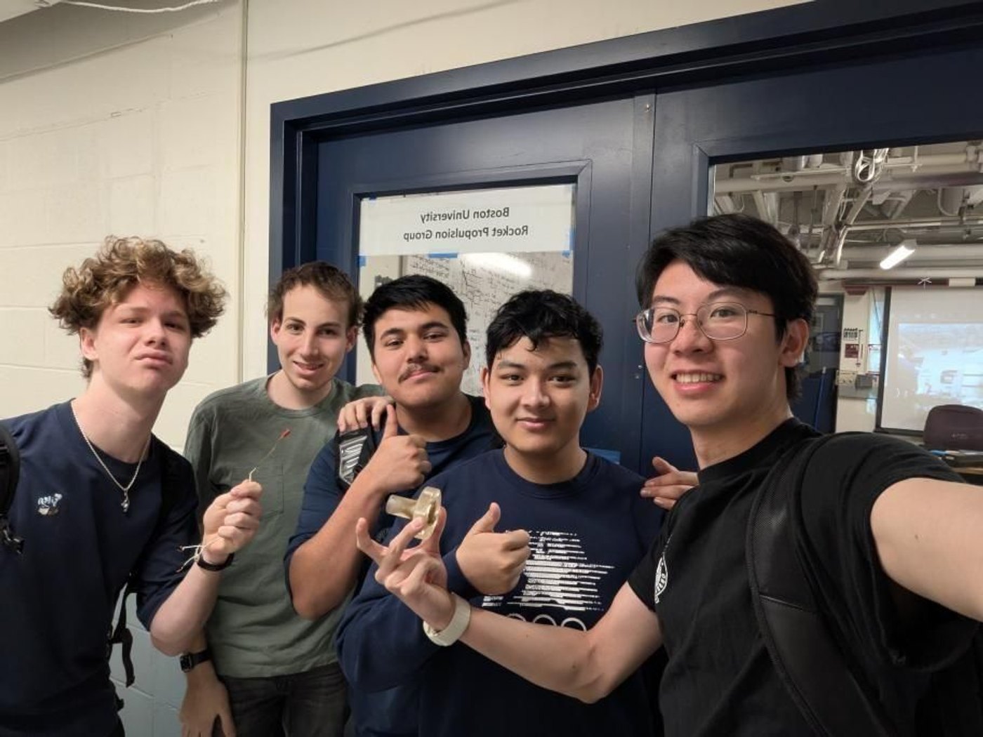
A team project with Boston University Rocket Propulsion Group (BURPG) to design and 3D print a rocket nozzle, plus the electronics to hot-fire it. Flow calculations sized the nozzle, SolidWorks FEA showed a minimum factor of safety of 2.1 at an 80 psi chamber pressure, and the printed nozzle was then hot-fired on a test stand.
- Role
- Team member (team of 5): design, CAD, FEA, 3D printing and testing
- Tools
- SolidWorks, SolidWorks FEA, 3D printing (ABS-like resin), Arduino Uno
- Mechanical
- Simulation
Problem
The brief was to build a rocket nozzle from a set of initial constraints, along with the electronics needed to hot-fire it and record thrust. The test was a static firing, so mass wasn't a design driver.
Approach
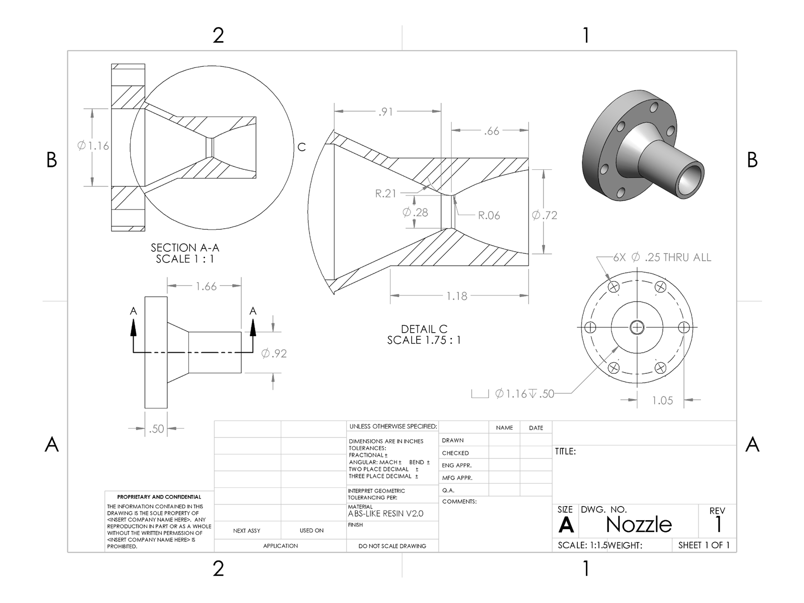
We built a spreadsheet from the textbook equations to size the nozzle from chamber pressure, assuming isentropic flow. It gave a specific impulse of 274.6 s, an exit velocity of 2,691 m/s, a critical pressure ratio of 0.578 (about 46 psi at the throat with an 80 psi chamber), an area ratio of 6.52, a 7.2 mm throat diameter, an 18.4 mm exit diameter and a 16.8 mm length (an 80% length nozzle).
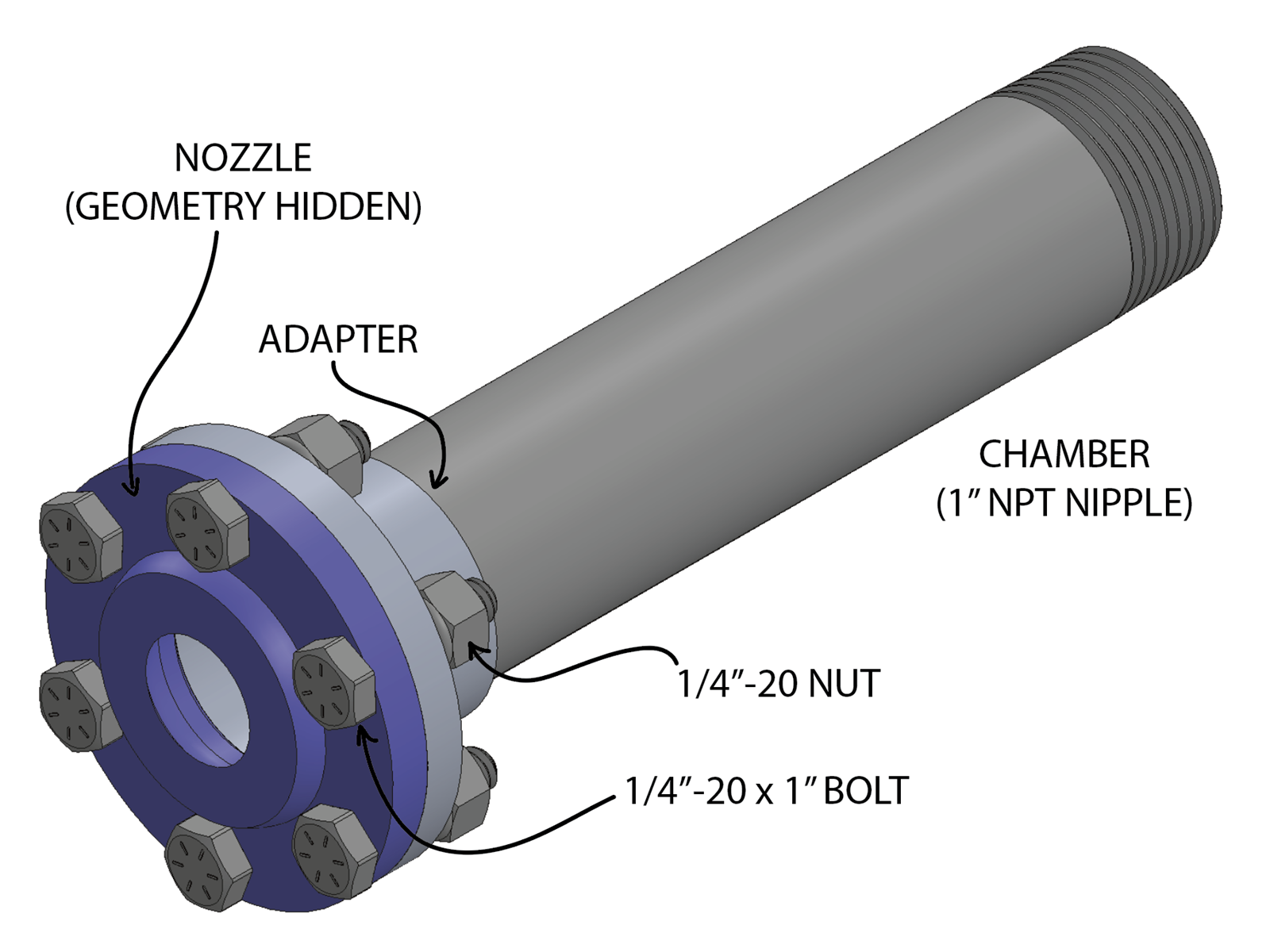
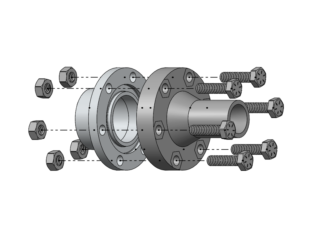
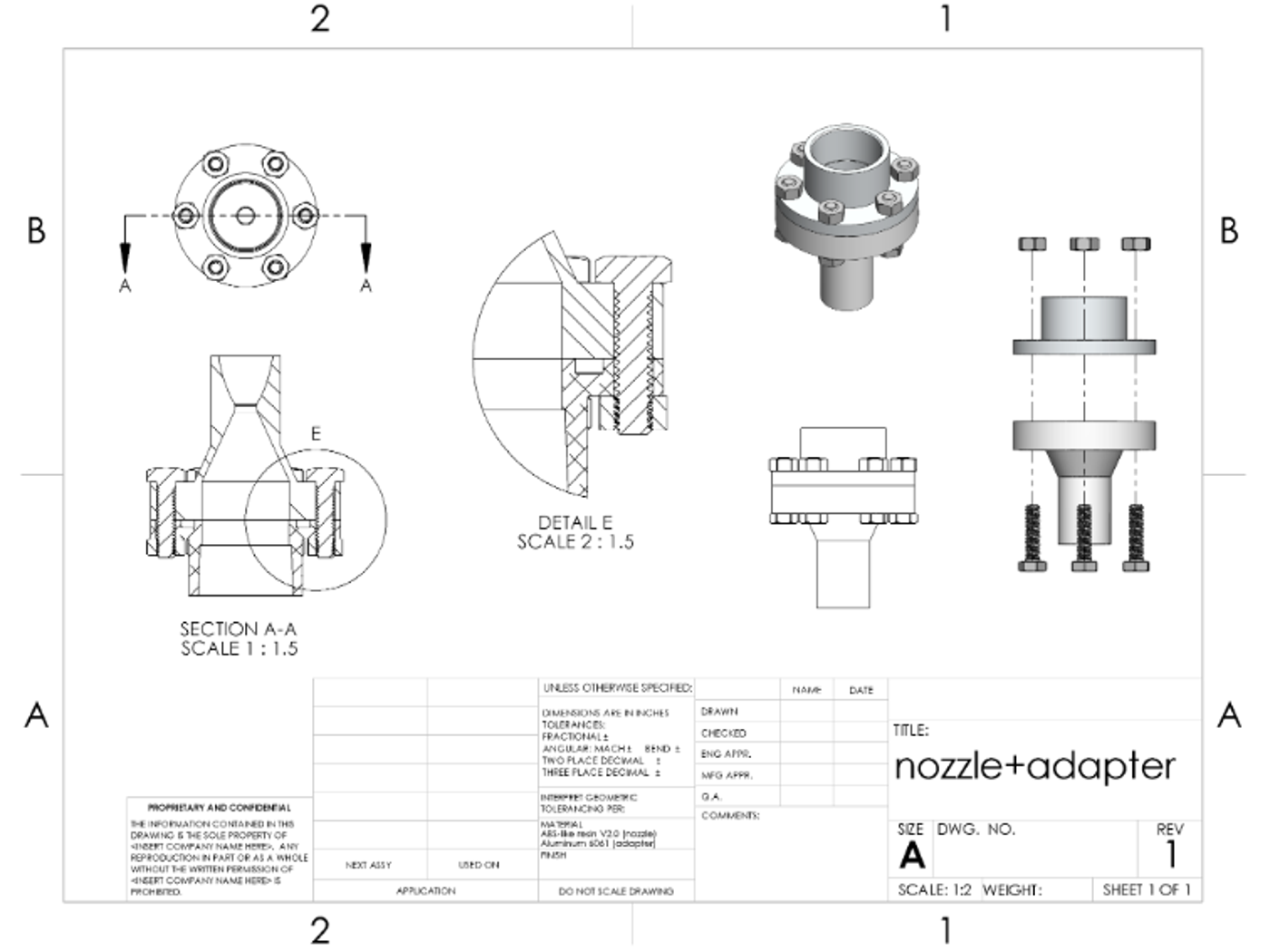
In SolidWorks the nozzle mates to an adapter on a 1 inch NPT chamber nipple through six 1/4-20 bolts and nuts. The calculated dimensions drive the geometry, and the part weighs 0.04 kg.
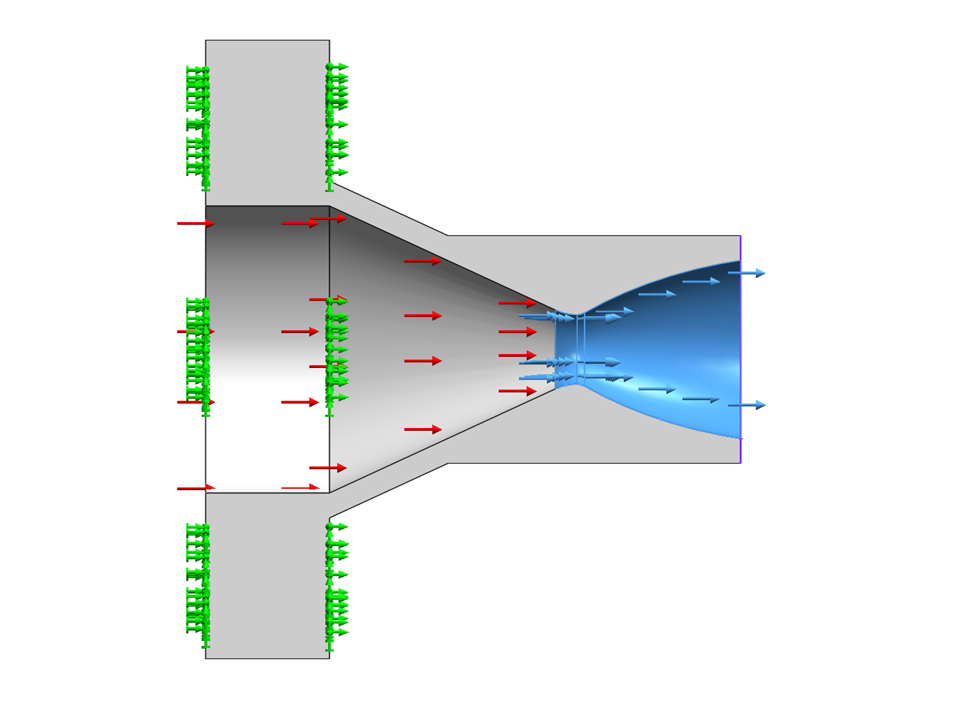
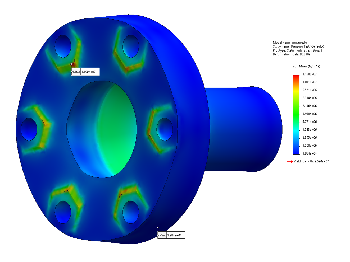
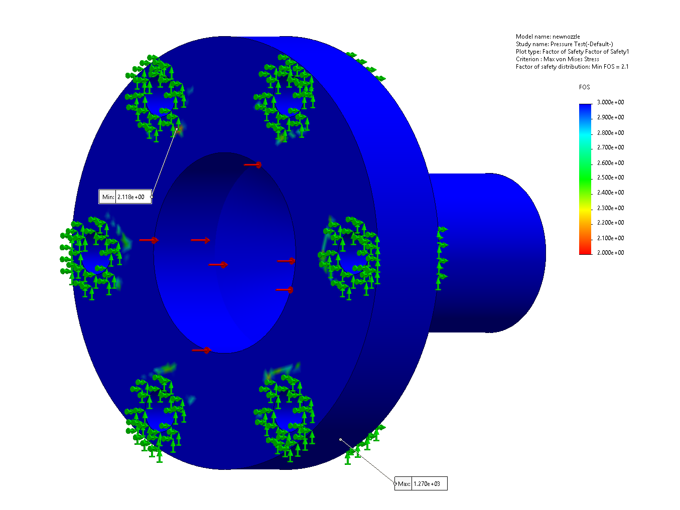
For the FEA we built a custom material from the resin's data sheet, taking yield strength as 70% of tensile strength (25.2 MPa). We applied 80 psi chamber pressure and about 46 psi throat pressure, with the six bolt-hole faces fixed.
We compared machining the part on a lathe, which is good experience but slow and impractical for several groups, with 3D printing, which only needs the CAD model but raised a concern about melting during the firing. We chose 3D printing in ABS-like resin. Heat transfer wasn't simulated, so we thickened the throat as a precaution and set the wall thickness at 0.1 in.
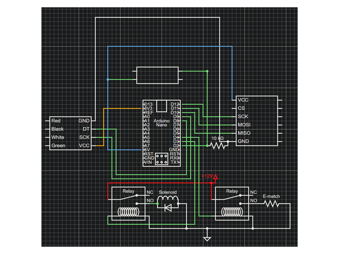
The test electronics use an Arduino Uno with a load cell and HX711 amplifier to record thrust, an SD card board to log the data, and a push button that starts the sequence. Relays switch the 12 V solenoid and the e-match, with a diode across the solenoid to block back-current.
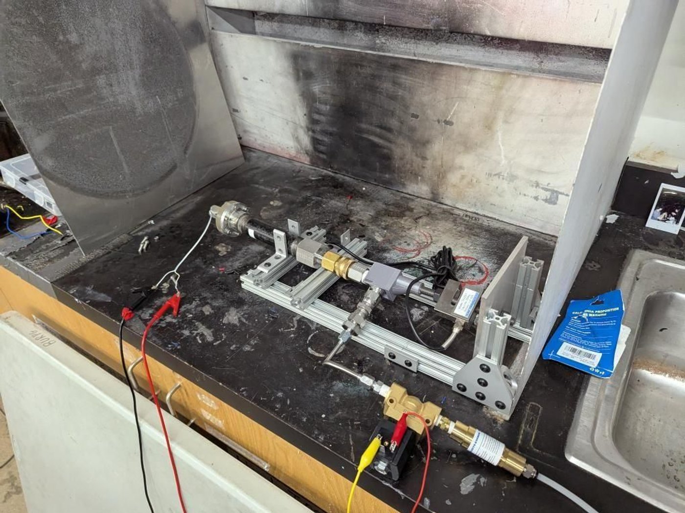
For the firing, the chamber and nozzle were mounted on an aluminum-extrusion test stand inside a fume hood, with the load cell in line to measure thrust.
Results
Calculated performance: 35.0 N of thrust at the optimal expansion and 11.8 N at sea level. The FEA gave a maximum von Mises stress of 11.9 MPa against the 25.2 MPa yield strength, and a minimum factor of safety of 2.118, above our target of 2, with most of the part above 3.
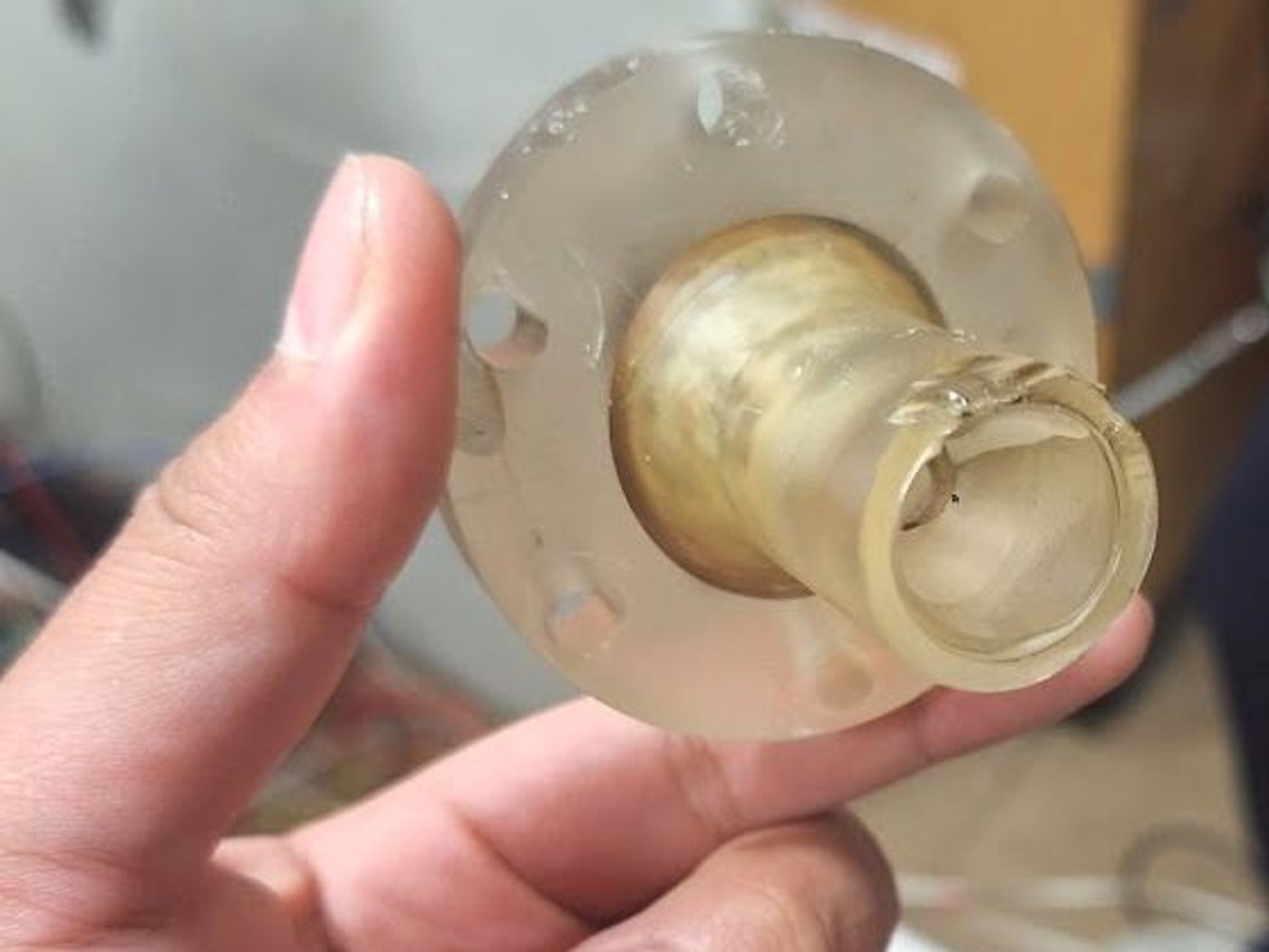
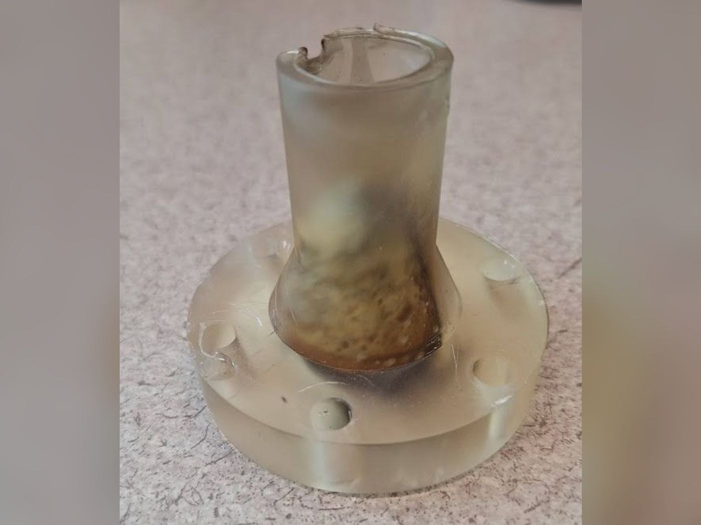
We hot-fired the nozzle on the test stand (video above). The printed part stayed intact: afterward its exit rim was chipped and its bore was scorched, which is the kind of heat damage we had flagged as a risk of printing it.
Gallery